Tubular reactor
A reaction rate learned inside a partial differential equation. The tube is discretised into 50 cells, so the model state has 50 entries, but only four sensors are measured. The example shows that a PDE needs nothing special from the library: the method of lines turns it into an ODE, simulate_fn returns the whole field, and state_to_output picks the sensor cells.
Read it after the hybrid ODE example, which covers networks inside the vector field on a small state.
Run it
uv run python examples/tubular_reactor/train_tubular_reactor.py
uv run python examples/tubular_reactor/train_tubular_reactor.py --steps 5 --no-plot  # smoke test
About two minutes on CPU at the default 600 steps per model. Prints both fits' metrics and the learned rate against the truth, and writes sensors.png, rate_law.png and field.png to examples/tubular_reactor/figures/.
The model
Liquid flows through a tube of length
The inlet concentration is held at the feed value, which drops to 30% at
Transport is known. The rate law is not. The data come from Langmuir-Hinshelwood kinetics,
with
The comparison model assumes first-order Arrhenius kinetics, Parameters.
Each sensor samples eight random times per experiment, so the four channels never share a time grid and the dataset is 76% masked.
Code
The discretised transport operator and the solve. step_profile builds the inlet concentration from the experiment's covariates, and solve_tube returns the diffrax Solution, from which the library reads ys:
def transport(c: Array, c_in: Array) -> Array:
    """Upwind advection and central dispersion, inlet held at ``c_in``, zero-gradient outlet."""
    left = jnp.concatenate([c_in[None], c[:-1]])
    right = jnp.concatenate([c[1:], c[-1:]])
    return -VELOCITY * (c - left) / DZ + DISPERSION * (left - 2.0 * c + right) / DZ**2


def solve_tube(g_fn, ts: Array, covariates, y0: Array, solver: hm.SolverConfig) -> diffrax.Solution:
    """Integrate the discretised tube for a rate ``g_fn(c, T) * c``."""
    temp, feed = covariates["T"], covariates["c_feed"]
    c_in = hm.step_profile(before=feed, after=0.3 * feed, jump_at=T_DROP)

    def vector_field(t, c, args):
        return transport(c, c_in(t)) - g_fn(c, temp) * c

    # The framework reads the state at ``ts`` from the Solution's ``ys``.
    return solver.diffeqsolve(diffrax.ODETerm(vector_field), ts, y0)
The hybrid evaluates the network once per cell with hm.evaluate_predictor, which vectorises over the 50 cell concentrations at the run's temperature. The observation map indexes the sensor cells:
def simulate_hybrid(predictors, ts, covariates, y0, solver):
    # One network call per cell: c is the [N_CELLS] field, T is shared along the tube.
    def g_fn(c, temp):
        return hm.evaluate_predictor(predictors["g"], {"c": c, "T": temp})

    return solve_tube(g_fn, ts, covariates, y0, solver)


def state_to_output(state: Array) -> Array:
    return state[..., SENSOR_CELLS]
The two models share the observation map, channels and solver; only the predictors and the simulator differ:
net = hm.BoundedPredictor(
    inner=hm.MLPPredictor(
        in_size=2, out_size=1, width_size=16, depth=2, activation_name="tanh", key=key
    ),
    input_keys=("c", "T"),
    input_bounds=((0.0, 2.2), (300.0, 360.0)),
    # g spans two decades over the box, so the output is log-warped.
    out_scaler=hm.BoundScaler(bounds=(0.05, 20.0), warp="log"),
)
hybrid = hm.HybridModel(
    predictors={"g": net},
    simulate_fn=simulate_hybrid,
    state_to_output=state_to_output,
    output_channel_names=CHANNELS,
    solver=SOLVER,
)
# Same sensors and solver; only the rate law differs.
mechanistic = hm.HybridModel(
    predictors={
        "k_ref": hm.Parameter(1.0, bounds=(0.05, 50.0), warp="log"),
        "Ea_over_R": hm.Parameter(2000.0, bounds=(0.0, 10000.0)),
    },
    simulate_fn=simulate_mechanistic,
    state_to_output=state_to_output,
    output_channel_names=CHANNELS,
    solver=SOLVER,
)
Both train with the same two phases. The first sees only the first half of each experiment, the start-up front, before the feed drop:
config = hm.OptaxTrainingConfig(
    phases=(
        # Fit the start-up front first, then the whole run with the feed drop.
        hm.TrainingPhase(args.steps // 3, lr=1e-2, horizon=0.5),
        hm.TrainingPhase(args.steps - args.steps // 3, lr=3e-3),
    ),
    verbose=False,
)
Solver and adjoint
The stiffest mode of the discretised operator is dispersion, at about Tsit5 takes a few hundred steps per solve. Halving Kvaerno3 takes fewer steps.
The config sets adjoint=diffrax.RecursiveCheckpointAdjoint(). The backward pass goes through the network at every cell and every solver step. The library's default, DirectAdjoint, stores that whole tape and compiles in time that grows with max_steps. Recursive checkpointing stores ADJOINT_REGISTRY in jaxhybridmodels.solver for the other choices.
Results
Default settings, seed 0. Sensor noise has standard deviation 0.01.
| model | RMSE z25 | RMSE z50 | RMSE z75 | RMSE outlet | worst |
|---|---|---|---|---|---|
| hybrid, learned | 0.011 | 0.010 | 0.009 | 0.011 | 0.999 |
| first order, fitted Arrhenius | 0.078 | 0.075 | 0.089 | 0.080 | 0.952 |
The hybrid fits to the noise level. The first-order model misses by about eight times the noise, and its
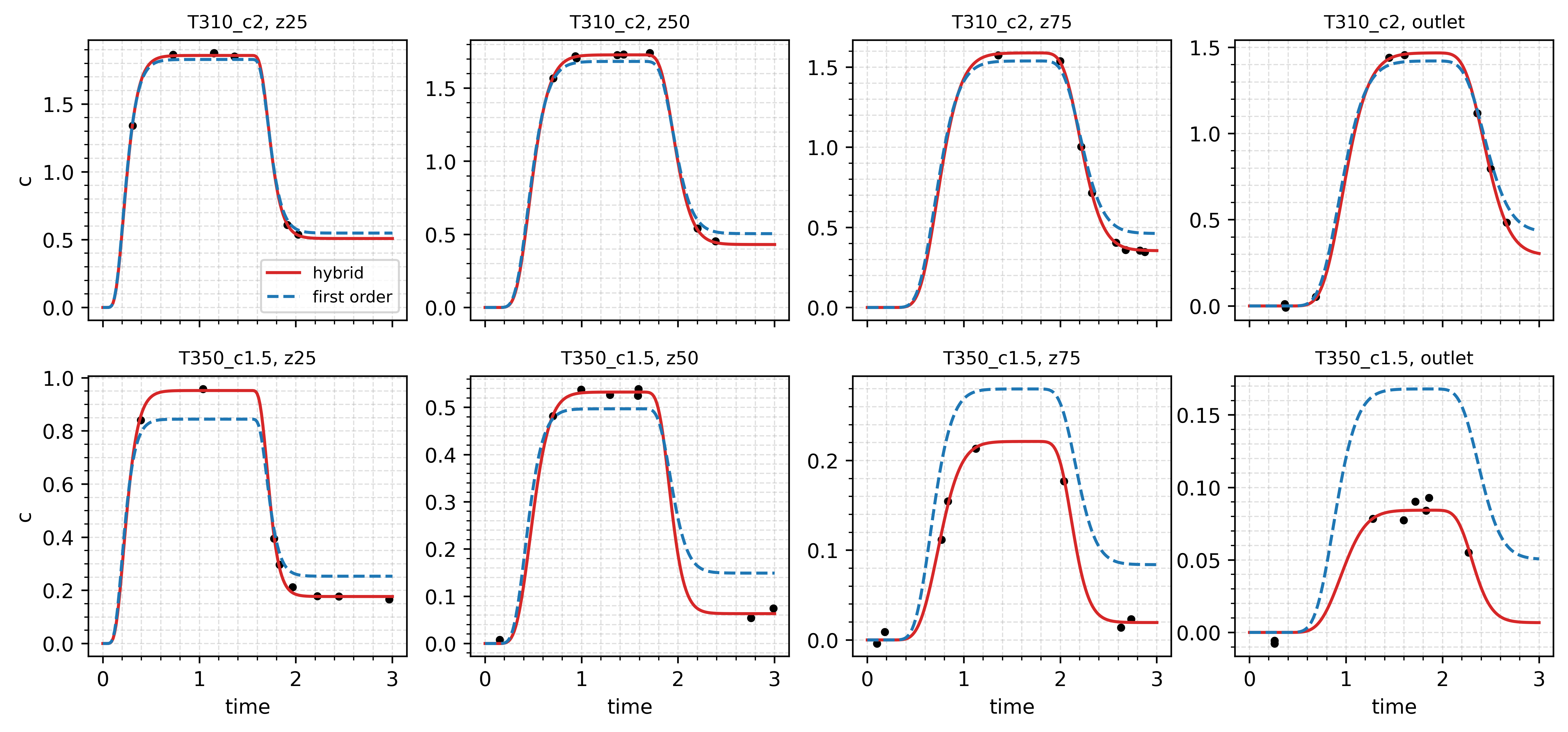
The first-order model also gets its constants wrong. It fits
The learned rate law matches the truth across the measured box:
| true | learned | ||
|---|---|---|---|
| 0.2 | 310 | 0.196 | 0.196 |
| 1.5 | 310 | 0.515 | 0.524 |
| 0.2 | 350 | 0.857 | 0.840 |
| 1.5 | 350 | 2.249 | 2.264 |
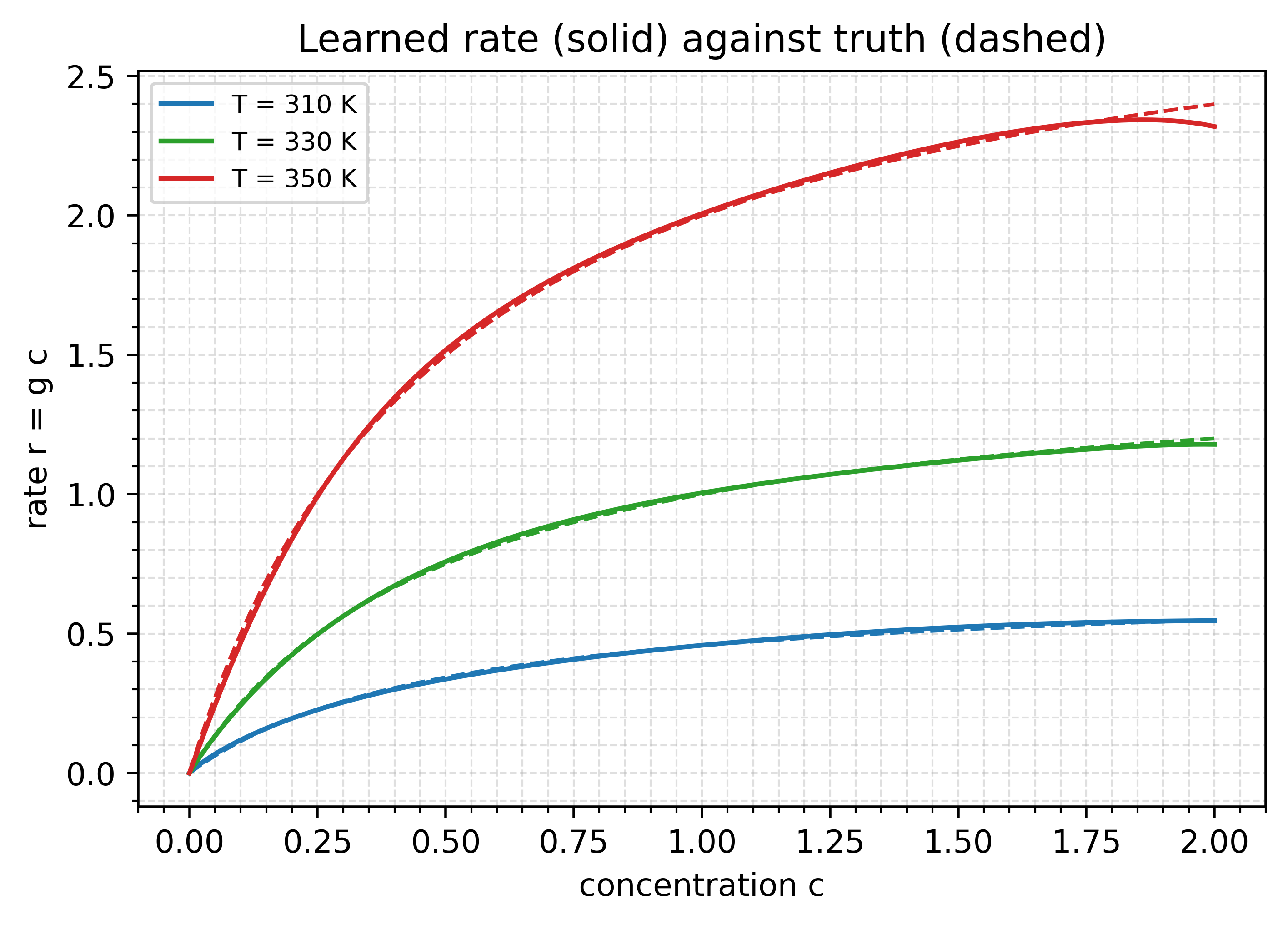
At 350 K the learned curve bends away from the truth above
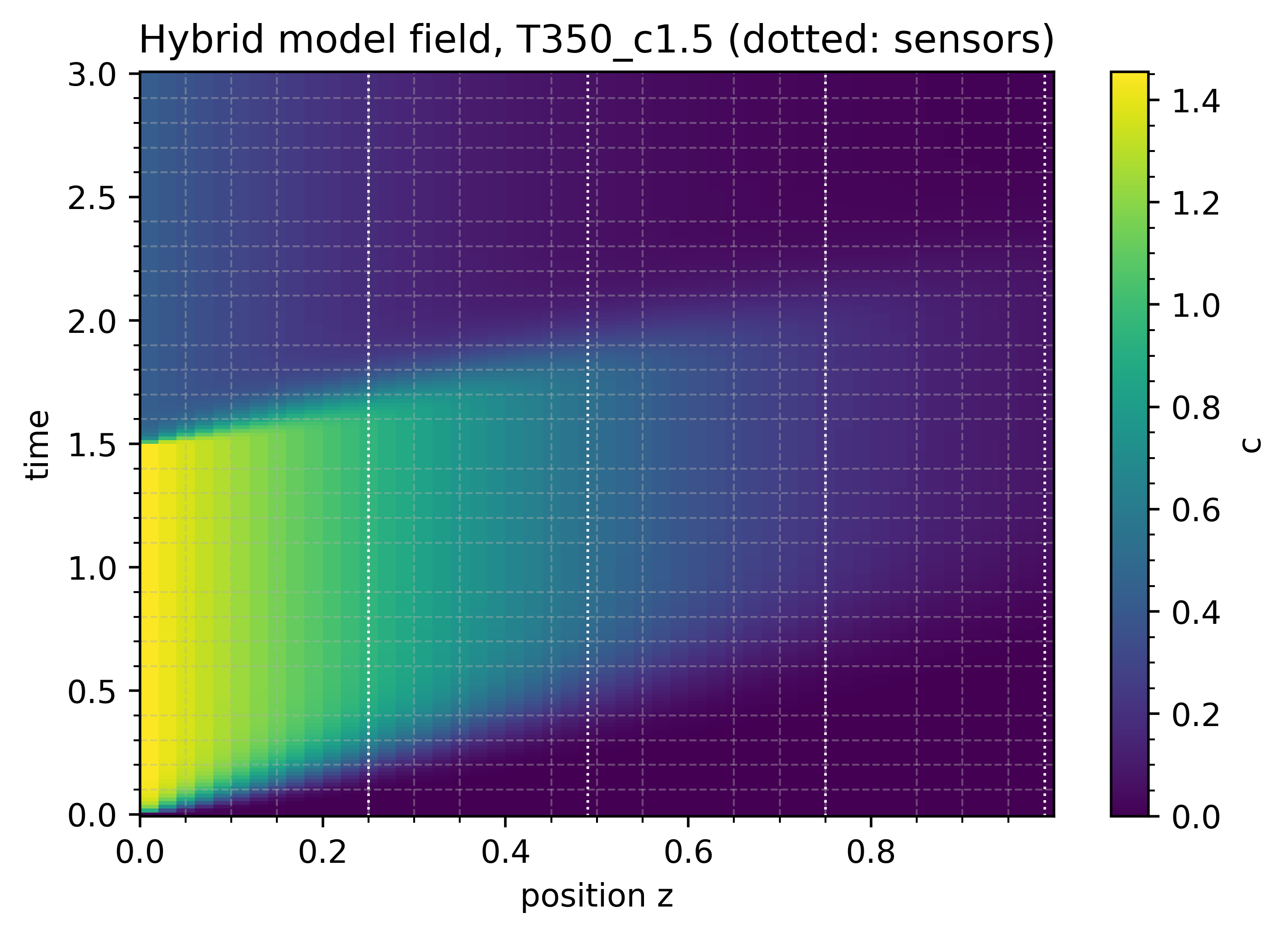
The full field of the hottest run shows what the sensors sample: the start-up front, the feed drop at
Things to try
- Change
N_CELLSto 200 and time a run withdiffrax.Tsit5()againstdiffrax.Kvaerno3(). - Keep only the outlet in
SENSORSand compare the recovered rate law. One channel sees the integrated effect of the whole tube. - Replace
RecursiveCheckpointAdjointwithdiffrax.DirectAdjoint()and compare compile time and memory. - Add a hot experiment with feed 2.0 to
CONDITIONSand check that the learned curve at 350 K follows the truth to.